NX7U
Scott Townley
Bridgewater, NJ
Coordinate System
All diagrams, graphs, etc. use a spherical coordinate system with azimuth (phi) defined in a right-hand sense from the x-axis in the x-y plane; and zenith (theta) defined from the z-axis. This is the spherical coordinate system used by NEC-2. Note that zenith angle=90-elevation angle. All antenna patterns are oriented for maximum radiation along the z-axis (theta=0).
The Model
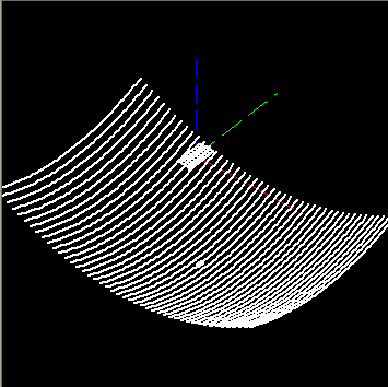
An actual BBQ grid dish obtained from K5GNA was measured. From the measurements the focal distance and f/D ratio in the horizontal and vertical planes can be calculated. Using an Excel spreadsheet, a NEC wire grid model was developed to match the measured dimensions of the grid dish, including the exact wire grid spacing and wire diameter. Therefore, any shortcomings in the model of the reflector should be NEC-intrinsic rather than due to model simplification.
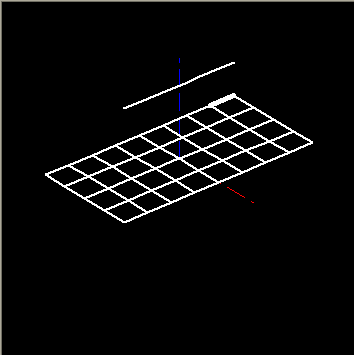
Then the integrated-dipole-plus-reflector feed was measured and modelled. In this case, the reflector is modelled using a rectilinear wire grid, so there is some degree of approximation.
The model wireframe drawings are shown below. These models are available for your use. They are in "native" NEC command line format. After you take receipt you're on your own. I can't help with translating it to EZNec or anything else. I was trained old-school :-)
Primary and Secondary Patterns
The professional terminology is to refer to the radiation pattern of the reflector feed alone as the "primary pattern", and to the pattern of the feed+reflector as the "secondary pattern". The NEC-2D calculated primary and secondary patterns are shown below.
Note that the peak gain of the secondary pattern is 25.5 dBi. This is a bit higher than the manufacturer-quoted value of 24 dBi. A "perfect" 38" x 24" aperture would have a gain of 26.76 dBi, so the modelled total efficiency is 25.5 - 26.76= -1.25 dB or 75%. This deserves some further consideration.
Primary pattern (AIDC3733 feed only), H-plane copolar Primary pattern, E-plane copolar
Secondary pattern, H-plane copolar Secondary pattern, E-plane copolar
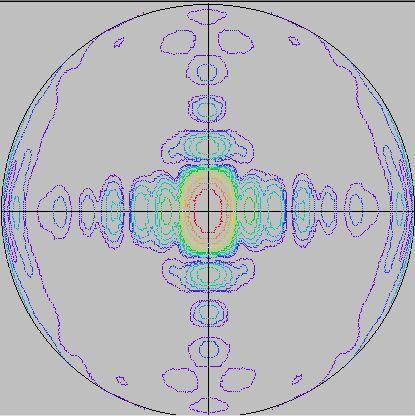
This is the "RDP" (radiation directivity pattern) of the entire feed+reflector system. Contours are in 3dB increments. The coordinate system is (u,v) space (or sin-theta space).
(u,v) space transforms thusly:
u=cos(phi)*sin(theta)
v=sin(phi)*sin(theta)
Then on this chart, phi is simply rotation, but the radial distance is sin(theta). The center is (0,0) or theta=0 degrees (z-axis), and the rim is theta=90 degrees or the x-y plane. The radius of the chart is 1 (in u-v space). The x-axis is the E-plane copolar cut and the y-axis is the H-plane copolar cut.
The utility of the RDP is that you can see everything at a glance, at least in one hemisphere.
This chart represents the entire front-hemisphere radiation (0<theta<90) of the BBQ dish. I have oriented this chart so that with the antenna mounted horizontally-polarized with respect to earth, the RDP is properly oriented...the top of the chart is directly overhead, the bottom is directly underneath, etc. Note that the main beam is "squished" in "elevation" when mounted horizontally, which is what you'd expect (more aperture, less beamwidth).
Note the higher sidelobes in the copolar H-plane (elevation plane if mounted for horizontal polarization). This is due to the low feed taper in the "long" dimension of the aperture.
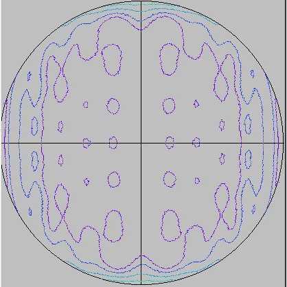
This RDP is the rear hemisphere of the antenna (the entire backlobe region). The axes are the same. The contour scheme is the same; each successively colored contour is 3dB change. There are 12 total levels in a roughly ROYGBIV (rainbow) order.
Note the conical-shaped backlobe that occurs approxmately +/- 120 degrees from boresight (theta=120, or radius=0.866 on this graph). A conical sidelobe has a u-v space contour that is a circle centered on the origin (or nearly so), as it occurs for all phi, so it is shaped like a cone.
Spreadsheet Analysis of Taper and Spillover Efficiency
Unfortunately, it is not a straightforward task to calculate the taper or spillover efficiency of this reflector. It would be, if it were circular, because then we can define the extent of the reflector using a single variable (the reflector's subtended angle to the feed). In that case, one can find the spillover and taper efficiencies from direct numerical integration of the modelled primary pattern [Balanis, Antenna Theory, Analysis, and Design, Harper&Row, 1982, p. 627].
The calculation will follow...but for now let it suffice to say that by hand, I was able to calculate a total system efficiency within 0.2dB of the NEC-inferred value of -1.25dB. Not bad!
Beam Efficiency and Antenna Noise Temperature--Horizontally Polarized
Beam Efficiency is the relative amount of total radiated power contained within a specified angular region. Beam efficiency can used as a figure-of-merit in dividing radiation patterns into desired (main-beam) and undesired (sidelobe) portions. Typical applications of beam efficiency would be in the determination of spillover loss in a primary (feed) pattern, or in the determination of total backlobe power in a secondary (total) pattern. For the primary pattern, utilized with a circular reflector, the spillover loss would be 10*log(beam_efficiency) where the beam efficiency is determined at the angle corresponding to the subtended angle of the reflector. For the secondary pattern, total backlobe power could be defined as (1-beam_efficiency) where beam efficiency is determined at theta=90 degrees.
Antenna Noise Temperature is the total thermal noise power (restated in terms of absolute temperature) available at the antenna terminals. Antenna noise temperature is critical to satellite system performance, since it contributes directly to the overall system noise temperature (G/T=gain/(RXsystem_noise+ANTnoise). In the following examples, antenna noise temperature is calculated as follows: First, a complete 3-D pattern in 1-degree increments is generated (64,800 data points). For whatever reason I call this type of pattern an RDP (radiation directivity pattern). Old habit, I guess. The RDP is then rotated for maximum radiation at 0 degrees elevation. For every RDP point, if the rotated angular point would intersect the ground (a plane defined at theta=90 degrees, or the x-y plane), a noise power of (directive_gain*earth_temperature) is assigned to that rotated angle. If the rotated angular point does not intersect the x-y plane, a noise power of (directive_gain*sky_temperature) is contributed to that rotated angle. Then the total antenna noise temperature at that elevation angle is calculated as [Johnson and Jasik, Antenna Engineering Handbook, 2nd Ed., McGraw Hill 1984, p. 41-7]
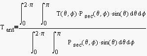
where T(theta,phi) describes the directional dependence of the noise temperature seen by the antenna. Note that for any axially (z-axis) symmetric pattern, the antenna noise temperature at elevation=0 degrees is (Tgnd+Tsky)/2, since exactly 1/2 of the antenna pattern strikes the warm earth, and 1/2 of the antenna pattern "sees" the cold sky. This conclusion is interesting, since it means that at zero elevation (AOS/LOS) gain alone differentiates two competing antennas. However, at higher elevations, even an antenna with lower gain can prove superior (higher G/T) due to lower sidelobe levels.
<some image here> The antenna analyzed here is a 2' prime-focus round dish, f/D=0.39. The feed is a simple turnstile (crossed-dipole) on a 4" round ground plane. Boresight gain=22.5dBic (calculated from NEC-2D). The edge illumination is -12dB (feed taper plus space loss).
Beam efficiency can be used to make system comparisons. For this antenna,
-The (one-sided) half-power beamwidth is about 7 degrees. 1/2 the total energy is within the half-power beamwidth.
-Backlobes (behind the reflector) are only about 6% of the total energy radiated.
Noise temperature is another indicator of sidelobe levels. Note how the noise temperature declines rapidly to about the 1st null beamwidth (13 degrees). At this point, the main beam does not contribute any warm-earth/ground noise. The noise temperature continues to decline slowly with increasing elevation, as the higher-level close-in sidelobes are pointed to cold sky.
<another image> This antenna is the 38"x26" BBQ grid dish with AIDC3733 integrated dipole/reflector feed. Peak gain 25.5dBiL=22.5dBic (exactly equal to the turnstile).
Compared to the turnstile/prime focus feed above, note that:
-The main beam efficiency is about the same (0.5), considering the average half-power beamwidth (which is not uniform).
-Sidelobe performance is significantly worse, with the beam efficiency not reaching 80% until encompassing nearly the entire front hemisphere.
-Backlobe performance is significantly worse as well, with only 82% of the total energy in the front hemisphere.
-Lower elevation noise temperature performance is nearly identical to the turnstile feed, but upon reaching the first null beamwidth, noise does not roll off with increasing elevation angle. The beam efficiency curve indicated higher sidelobe levels, which directly results in higher noise temperatures.
Compare at 45 degrees elevation:
Noise temp of turnstile=30K
Noise temp of BBQ=47K
Loss of G/Tant=10*log(30/47)= -2.0dB (since gains are identical, only need compare temperatures).
This isn't quite a fair comparison, as there is receiver system noise to consider. The noiser the receive system, the less impact the antenna G/Tant has on the overall G/Tsys. For example, if I had a receiver chain NF of 0.5dB (=35K) (red-hot downconverter with enough gain to swamp out my receiver/coax losses),
G/Tsys=177.83/(35+30)=4.37dB for the red-hot turnstile+dish system
A more pedestrian system, say with a DEMI downconverter with a noise figure of 1.2dB (=91K)
G/Tsys=177.83/(91+30)=1.67dB for the pedestrial turnstile+dish system
But using the integrated downconverter AIDC3733 with a noise figure of 1.2dB,
G/Tsys=177.83/(91+47)=1.08dB for the BBQ system
So while the grid dish is certainly not a red-hot system (giving up 3.3dB in G/Tsys), in this modelling routine it is not distinguishable (0.59dB difference) in performance from a good 2-foot round dish using a common downconverter.
Beam Efficiency and Antenna Noise Temperature--Vertical Polarization
Same bit, but now the antenna oriented longways-horizontal, for vertical polarization.
<some image here> Naturally the antenna beam efficiency will be no different for vertical polarization. BUT, notice that the antenna noise temperature is lower in the 10-20 degree elevation region. This is directly due to the lower sidelobe levels/fewer sidelobes in the E-copolar plane.
Once elevation hits 30 degrees, the entire conical backlobe at +/-120 degrees from boresight sees the warm earth, and the antenna noise temperature is very close to that of the horizontal case.
The 14K or so difference will only be noticable with very low noise figure downconverters, however. For the integrated AIDC3733 downconverter with a nominal noise figure of 1.2dB, the difference in Tsys at 10 degrees elevation is (92+60)/(92+46)=1.101=0.42dB in G/T...so there is not a practical advantage to mounting the grid dish for vertical polarization.
Concluding Remarks
This study was undertaken to try and quantify some of the controversy surrounding the use of this type of grid-dish antenna on AO-40. I will leave the reader to draw any qualitative conclusions, since other factors such as economics, the XYL/OM, etc., can be as or more important than raw engineering performance. Personally, however, I have made many contacts on such a grid-dish, under some challenging conditions.
About the Models and Software
The modelling engine was NEC-2D, available from The NEC-Archives. They were run on an AMD Athlon PC with a 1200MHz clock speed. The RDPs took about 15 minutes to complete (they are the longest since 64,800 pattern points are calculated).
Wire grid models were built by hand, using Microsoft Excel. Formulas were developed to describe the appropriate wire curvatures, which were then exported to text files in NEC input format. This method saved a LOT of typing, and typos!
The wiremesh display program was written by myself in Visual Basic, using a wiremesh generation algorithm found in the NEC-Archives, and largely based upon Bob Just's pioneering work NECDraw (particularly in implementing model verification and rules-checking routines from an article by Trueman). Unfortunately NECDraw has a hard-coded limit of 1000 segments, which isn't enough for these larger models. I was fortunate enough to work with "Just Bob" when he developed NECDraw and gave it away at the ACES Conference (1993) in Monterey, CA. Long live the "Red Badge of Courage", Mon!
The pattern displays, antenna noise temperature calculation/graph and beam efficiency calculation/graph was written by myself, again in Visual Basic. They are original. The RDP contour output was based on a contour-plotting algorithm "CONREC" by Paul Bourke (from Byte Magazine...remember that?) who was kind enough to supply a Visual Basic example implementation on his website. This freebee saved me hundreds of hours of programming!
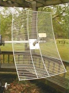
In the "good old days" of AO-40, K5GNA was the source for "Barbecue Grid Dishes" for Mode S. Originally used for point-to-multipoint instructional television (since reallocated in the US to Clear-brand WiMax), this antenna system included a Transystem AIDC3733 downconverter with an integrated dipole/splash reflector feed arrangement.
This system proved to be a very popular entry point for AO-40. It was linearly (rather than circularly) polarized, which represented something of a performance compromise, particularly for high squint angles. And there was plenty of discussion on AMSAT-BB about using it vertically polarized vs. horizontally polarized (the picture shows the latter), along with covering the grid with fine-mesh aluminum screen.
The article that follows was an attempt at determining the truth (or at least more of it) with respect to using this antenna system for satellite operations. Originally web-published in 2003.
K5GNA system, with 38" x 24" wire reflector grid, integrated dipole/splash reflector feed system.
Closeup of the integrated dipole (top) and splash reflector
A bunch of pieces missing due to ISP failure in the past. Eventually I'll fill in the blanks...


")
")