NX7U
Scott Townley
Bridgewater, NJ
Backfire?
There are two broad classes of helical antenna, the endfire and the normal-mode. "Normal" in this usage indicates "perpendicular" rather than "customary", and describes many rubber-duck and small omni-directional antennas. "Endfire" is what we are typically referring to with helical antennas--it radiates "off the end" of the antenna.
A further distinction of endfire is in the direction it radiates. For whatever reason, the customary endfire direction is the end opposite the feedpoint. Perhaps because it's intuitively satisfying--put it in there, it goes down the helix, comes out the other end. Backfire on the other hand is the exact opposite. Maximum radiation occurs in the direction of the feed. For example, the quadrifilar helix is generally configured for backfire radiation.
This article describes a backfire helix feed used for an AO-40 receive antenna operating at 2401MHz. The prime-focus reflector used is 24"/60cm in diameter, and has an f/D ratio of 0.39.
Description
Nakano[1] has published an excellent design reference for small helical antennas. In his paper, he shows that the customary endfire condition exists when the ground plane/reflector for the helix is at least 0.5 wavelengths in diameter. However, as the ground plane is made smaller, the front-to-back ratio degrades rapidly to 0dB (equal endfire and backfire), and then actually transitions to a nearly pure backfire for a ground plane/reflector diameter of 0.29 wavelengths. If nothing else, the paper provides solid design guidelines for sizing the reflector for a customary endfire helix!
The remarkable thing about this class of backfire helix is the quality of the pattern generated. Nakano calculated very clean patterns with very low sidelobes, excellent circularity (axial ratios under 1dB within the half-power beamwidth), and excellent (>20dB) front-to-back (or is that back-to-front?) ratios. One limitation of the class is that the gain is relatively fixed between 7dBic and 11dBic, so their application to dish feeds is generally limited to smaller f/D ratios (keeping the edge illumination in the -10dB range).
One very important observation is that the backfire helix radiation is of opposite sense to the helical winding. So to build a LHCP antenna for a reflector feed (which ends up RHCP upon reflection), the helix has to be wound RH. Confusing!
The Antenna Structure
Nakano shows several models of backfire helix with variable pitch swept over a frequency range of 7 to 13GHz. The 14 degree pitch model looked very good at 10GHz, with a front-to-back ratio of 20dB, an axial ratio of 1dB, and a 10dB beamwidth of about 130 degrees (although this looks a little wide for f/D=0.39, the space taper factor will result in the desired 11dB edge illumination). So I generated a NEC-2 model of this antenna, scaled down to 2.4GHz. The scaled dimensions are:
NEC-2 Input Deck
CM Nakano et. al., "Backfire Radiation from a Monofilar Helix with a Small
CM Ground Plane", IEEE Trans. Ant. Prop., Oct. 1988, p. 1359.
CM This example, in section III, p. 1361. is
CM nearly an exact match to presented data (scaled here to 2.4GHz)
CM this antenna phase center is 1.1" into the helix from the GP
CM
CM Coded NX7U 2003-03-16
CE
GW100,2,0.,0.,0.,.59056,0.,0.,.049 ! 8-spoke ground plane
GA102,1,.59056,0.,45.,.049
GM0,0,-90.,0.,0.,0.,0.,0.,102.
GM0,7,0.,0.,45.,0.,0.,0.,100.
GM0,0,0.,0.,0.,0.,0.,-0.164,100. ! -.275 is the GP-helix spacing
GH200,252,1.0225,7.1574,0.6527,0.6527,0.6527,0.6527,.049 ! pitch 14 deg
GW201,2,0.6527,0.,0.,0.,0.,0.,.049 ! axially (not circumferentially) fed
GW202,1,0.,0.,0.,0.,0.,-0.164,.049
GM0,0,-180.,0.,0.,0.,0.,0.,100. ! point it for maxrad +z
GM0,0,0.,0.,0.,0.,0.,1.1,100. ! phase centering
GS0,0,.0254
GE
FR0,1,0,0,2401.,1.
EX0,202,1,01,1.,0.
RP0,181,4,1000,0.,0.,1.,45.
EN
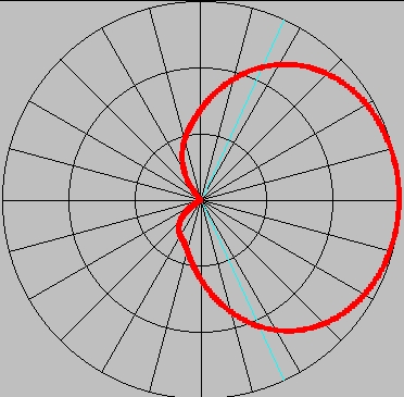
The blue lines are the subtended angle for the f/D=0.39 reflector. When the space taper is included, the polar pattern is -11dB at the blue line. Note that the axial ratio is better than about 0.7 (-1.5dB) across the entire subtended aperture. This is one of the strongest advantages of the backfire helix. I have not been able to get such a good axial ratio response from any form of cupped endfire helix suitable for a f/D=0.39 reflector.
The calculated input impedance Zin=96-j34 ohms. Also, note in the NEC file that the phase center was determined to be 1.1" into the helix. This can be done in NEC by adjusting the location of the pattern coordinate system (by sliding the antenna laterally) until the far-field phase response is constant across the aperture.
The taper (aperture) and spillover efficiencies can be calculated by integrating the feed's amplitude pattern over the subtended reflector surface. The expectation is that both efficiencies should be excellent, as the edge illumination is near optimum (-11dB) and the sidelobes/backlobes are nearly non-existant. Integrating the patterns yields a taper efficiency of 0.888 and a spillover efficiency of 0.898, for a total illumination efficiency of 0.888*0.898=0.797, very close the the theoretically optimum 0.81.
Impedance Matching
Since the helix isn't fed circumferentially like a customary endfire helix (it couldn't be--the helix is smaller than the ground plane!), a different approach to impedance matching is needed. I considered stubs and such when I realized that with a relatively low impedance, a single series-matching line transformer should be able to do the trick. A series-matching line section is a general transmission line of impedance Z and electrical length L. The quarter-wave transformer, with Z=sqrt(Z1*Z2) and L=90 degrees is a specific form of a series-matching line. Here, since some load reactance is involved, L will be different from 90 degrees.
The matching section calculations give Z=78 ohms and L=64 degrees. For a air-dielectric, a coaxial 78 ohm line would have a diameter ratio D/d=3.5+. 1/2" Cu pipe fits nicely over the end of a N-flange connector, so the center conductor would need to be 0.545"(type L 1/2" nominal i.d.)/3.5=0.156" or very nearly 5/32". Ace, True Value, and hobby shops all carry small diameter brass tubing for the inner conductor. The length would be 4.918"*64/360=0.875".
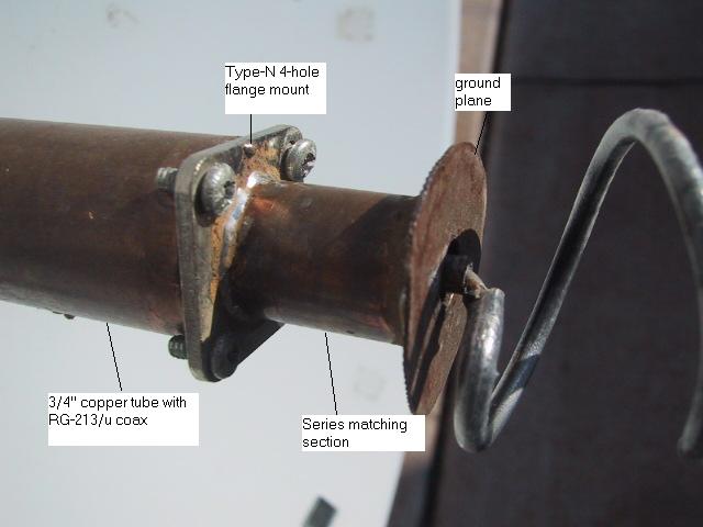
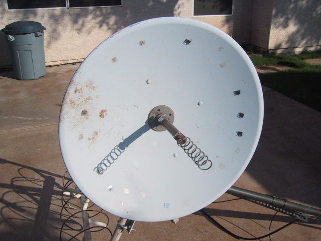
Viewing left-to-right:
The 3/4" copper tube is the support for the feed. This pipe is actually a 3/4" "repair" tube, so it telescopes over the standard type-L 3/4" Cu tube. At the dish vertex is a 3/4" pipe floor flange, which the support tube screws into. The two tubes telescope to allow adjustment of the feed to the dish focus.
The type-N flange has the threaded end pointing left, into the repair tube. The RG-213 cable simply screws into the connector. It is held to the repair tube by the side friction of the screws.
The series matching section is made of 1/2" Cu tube and 5/32" brass tube for a center conductor. The brass tube fits over the solder cup of the type-N flange mount.
The ground plane is 0.26wl, snipped from 0.040" copper sheet.
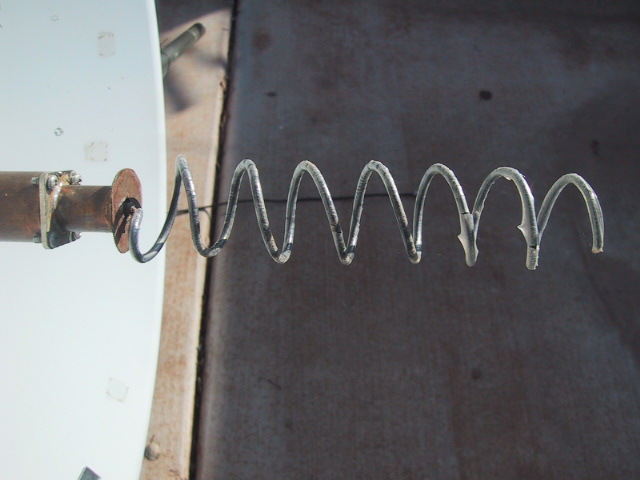
The helix is 12AWG. Note the helix is axially fed--the helix wire starts at the center, runs straight out to the helix radius, and then starts winding (RH) away. The spacing between the radial run and the ground plane sets the feed point impedance.
Slightly further away. The 12AWG wire was THHN house wire, and you can see the plastic coating flaking off. Nothing made of plastic lasts more than a year in Phoenix.
The grey center piece is the 3/4" floor flange that the feed support tube screws into. The other end of the 213 cable comes out the back of the dish and is terminated in another N-type cable connector, for attachment to the downconverter-du-jour.
Note the exceptionally small central blockage the feed has: 1.2" diameter out of 24" of aperture.
Measurements
The input impedance was measured using a calibrated Anritsu "Site Master" scalar network analyzer. Both unmounted and mounted, the return loss was better than -24dB (<1.2:1 VSWR). The fact that the swept return loss curve did not change its shape when mounted is an indication of excellent axial ratio. Naturally I did the "hand waving" exercise as well. Holding your hand in front of the free end of the helix did not affect the return loss sweep. However, cupping your hand around the tubing right behing the N-flange connector (maximum radiation) made the return loss curve dance. A rough indication that it really radiates backfire.
I do not have adequate facilities for sun noise measurements (yet), so I can't report on that just yet. However, the system seems to perform fairly well. It definitely "sounds" better than the old cupped endfire helix.
References
[1] "Backfire radiation from a monofilar helix with a small ground plane", Nakano, H.; Yamauchi, J.; Mimaki, H.; IEEE Trans. Antennas and Propagation, Volume: 36 Issue: 10 , Oct. 1988
Page(s): 1359 -1364
[2] "Generation of a circularly polarised conical beam from backfire helical antennas ", Nakano, H.; Mimaki, H.; Yamauchi, J.; (IEE) Seventh International Conference on Antennas and Propagation (ICAP), 1991. 15-18 Apr 1991, Vol. 1, Page(s): 42 -45.
[3] "A backfire helical feed", Johnson, R.; Cotton, R.; IEEE Trans. Antennas and Propagation, Vol. 32, No. 10, Oct 1984, Page(s): 1126 -1128.
[4] " Improvement of front-to-back ratio of backfire helical antenna", Yamauchi, J.; Nakano, H.; Iio, S.;
(IEEE) Antennas and Propagation Society International Symposium, 1982 , Volume: 20, May 1982.
Page(s): 370 -373
A "backfire" helix dish feed for 13 cm
| • |
Ground plane disc diameter 1.18" |
| • |
Helix diameter 1.36" (yes, the helix is larger than the ground plane) |
| • |
14 degree helix pitch |
| • |
Wire diameter 0.098" (approx. 12 AWG) |
Modelling Results
Amplitude pattern (reflector would be to the right, helix "pointing" to the left), 10 dB/div
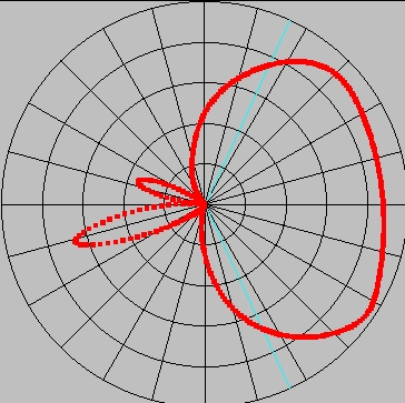
Axial ratio, same coordinates. 0.2 (linear)/div.


")
")