NX7U
Scott Townley
Bridgewater, NJ
Do I really need one of these for Mode J (aka V/U)?
Maybe not, but I bet you will. There are two additional operational difficulties associated specifically with Mode J:
Harmonic Radiation. With a 145MHz uplink, the third harmonic is 145x3=435MHz...that's right in the downlink band! Even if the frequencies don't exactly line up, there will be some energy impinging on your RX directly from your TX 3rd harmonic. And since we're trying to copy pretty weak signals, even "good" isolation between TX and RX isn't much. For example, with +50dBm TX ERP (100W), it would take 180dB isolation to knock the 3rd harmonic down to roughly noise level (+50-180=-130dBm, typically of a good receive system). Even with 60dB 3rd harmonic suppression from the TX, you need 120dB more and that's a lot! Since the interference is "in-band" to the RX, the solution lies elsewhere. Maximizing antenna isolation (by physically locating them as far apart as possible, and for a mobile station, even running TX and RX cross-polarized) helps a lot. Another help is a 2m TX bandpass filter to further reduce the 3rd harmonic.
Receiver Desense. This is particularly a problem with multiband radios (like the FT-100!). The front end of the V/UHF receiver is pretty much wide open; there's not a band-specific RX preselector filter or anything like that. So the (very) strong signal you TX on 2m is hitting the front end of your 70cm receiver very hard. Even though you're tuned very far away, the 1st RF mixer isn't and it has to handle all that energy. Quite likely it does this by compressing the desired 70cm input signal. You can tell you have RX desense if you can hear your voice or keying as if it were superimposed on broadband noise--no matter where you tune the RX, it's there. The solution--listen only to what you want. A bandpass filter in the RX line (ahead of any preamp) will do the trick.
An additional problem (but not necessarily limited to Mode J operation) is driving past high powered communications facilities. There are a LOT of 450-470MHz business band radios, repeater sites, pagers, etc., out there. Just driving past a cement truck with a 450MHz radio can render your RX useless (until you get past!). This problem really is intermod being formed in the 1st RF mixer of the RX, and the only way to solve it is to reject as much unwanted RF before it hits that mixer. Again, a bandpass filter is indicated.
The 1999 ARRL Handbook (and several other years, and the old VHF/UHF Manual by Jessop) have construction details for the "4x3x5" bandpass filter. A clever name: it's a coaxial cavity resonator 5" long, with a 4" center conductor, 3" in diameter, that works at 435MHz (hehehehe). I will describe its construction here, but the article in the Handbook is worth having.
Materials
A 5" long piece of 3" copper pipe. This is the hardest bit by far to find. Commercial plumbing shops will have it, but in 20' lengths. You might ask if they have any remnants. Otherwise your best bet is a metal salvage yard. All the rest you can get at the hardware store:
A 4" long piece of 3/4" copper pipe.
Some copper flashing, to fashion two 3/4" diameter discs.
Some more copper flashing for two 3" diameter discs; or you can use a 4" square piece of circuit board material.
Buss wire (about 14-16AWG)
Two panel connectors (BNC or N, stay away from SO-239 at this frequency)
A 1/4"x3" brass machine screw and 3 1/4" brass hex nuts.
Drill.
Propane torch to do most of the soldering.
Silver plumber's solder and flux.
Patience...
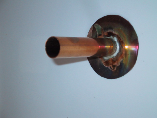
Solder 3/4" tube to center of bottom plate. If you use a circular bottom, center alignment is important.
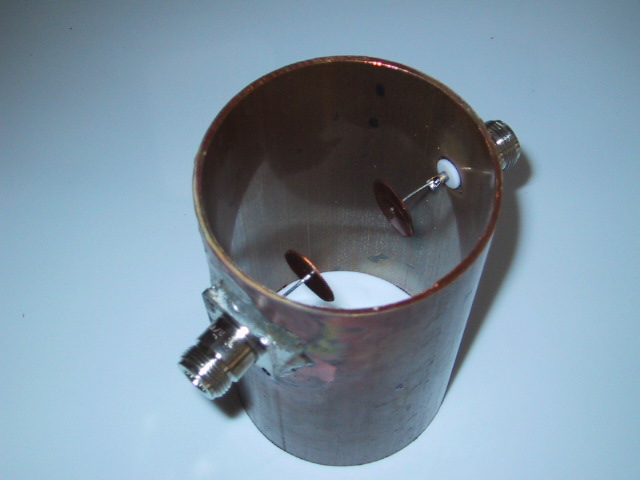
Drill two holes, 1-1/4" down from the "top" of the 3" pipe, for your connectors. Put the holes on opposite sides. Solder connectors in place. This is a difficult task; the pipe sinks a LOT of heat. Wear gloves! Also, if you use panel jacks, you'll note the problem of mating a flat surface with a curve; the sides of the panel flange will have quite a gap. You can try to flow plenty of solder in that gap to close it up (I did), or use some tinned braid to fill up the gap. For the coupling discs, drill holes just large enough to pass the buss wire in the center of both 3/4" discs. Solder the buss wires to each connector solder cup.
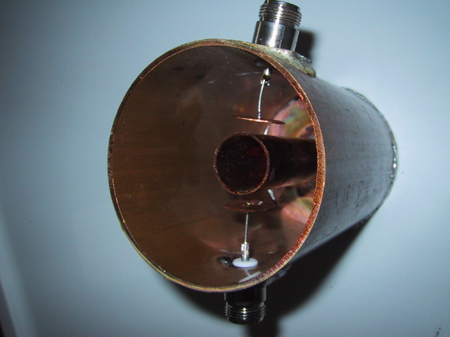
Place and align the 3" tube over the bottom plate/tube. Slip the discs on such that they are 3/16" spaced from the center (3/4") tube. Solder to buss wire. Get the torch back out and solder the bottom plate to the 3" tube.
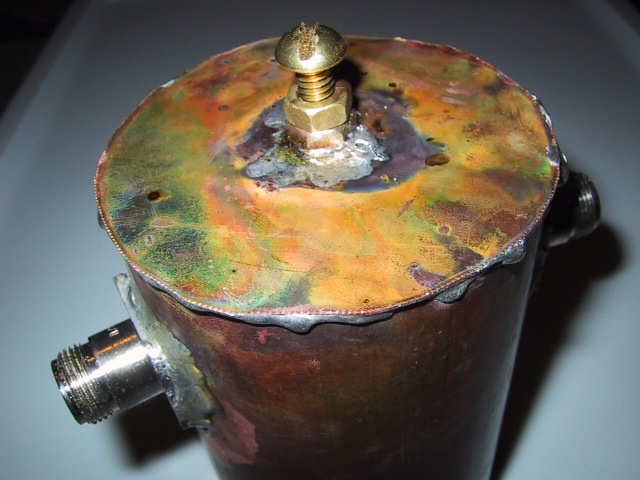
(Almost done!) Drill a clearance hole for the 1/4" brass screw in the center of the 3" diameter top cover. Carefully solder a 1/4" brass nut on both sides of the cover. I did this with the screw in-place, holding it all together, and the solder flowed into the nut threads and caused extra work cleaning it all out. Maybe a temporary stainless or zinc-plated screw would have done a better job...Now torch-solder the lid onto the full assembly with the stainless screw in place (otherwise the inside nut will fall off from the heat flow!).
Tuning
I have a 500MHz network analyzer but most won't be so fortunate...but basically you can tune for maximum signal through using a signal generator, or best match using a load on one port. My filter has a -3dB bandwidth of about 6MHz and -6/-60dB shape factor of about 1.65, without silver plating...pretty darned good! Note the tuning screw will be nearly all the way inserted in the end.
Of course, there are other ways to implement a 70cm bandpass filter, or you can buy one ready-made (DCI Inc. in Canada is one vendor). But the narrow bandwidth is a requirement if you expect to reject paging and two-way junk between 450-470MHz. Plus it can handle a fair amount of TX power (100 W easily).


")
")

